 |
|
|
Router Table

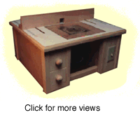
A router table is an invaluable tool. The problem, however, is that ready-built router tables are usually relatively expensive and too narrow for many projects. This router table provides a workable area of 15" (381 mm) which will allow you far more flexibility than a shop-bought model. Further, the back support can be removed from the table to allow for free-form routing, if so desired.
Construction
Tools required: Router, jigsaw, sander, drill
Wood required:
| Description | Qty | Width | Thickness | Length |
| Corner posts (Pine) | 6 | 1 1/2" (38 mm) | 1 1/8" (28.5 mm) | 11 1/2" (292 mm) |
| Side pieces (plywood) | 4 | 11 1/2" (292 mm) | 1/2" (13 mm) | 19 3/4" (501 mm) |
| Front corner supports (pine) | 2 | 1 1/2" (38 mm) | 3/4" (19 mm) | 4 1/2" (114 mm) |
| Switch panel (pine) | 1 | 4 1/2" (114 mm) | 3/4" (19 mm) | 11 1/2" (292 mm) |
| Drawer runners (pine) | 4 | 1/2" (13 mm) | 1/2" (13 mm) | 18" (457 mm) |
| Outer panel support | 2 | 1 1/2" (38 mm) | 3/4" (19 mm) | 18" (457 mm) |
| Back spacers | 4 | 1 1/2" (38 mm) | 3/4" (19 mm) | 4 3/4" (121 mm) |
| Center Supports | 5 | 1" (25 mm) | 1 1/2" (38 mm) | 11" (279 mm) |
| Top | 2 | 24" (610 mm) | 1/2" (13 mm) | 24" (610 mm) |
| Edging trim | 4 | 1 1/4" (32 mm) | 5/16" (8 mm) | 24 3/8" (619 mm) |
| Drawers (base) | 2 | 4 1/2" (114 mm) | 3/4" (19 mm) | 16 1/2" (419 mm) |
| Drawers (front) | 2 | 4 1/2" (114 mm) | 1/2" (13 mm) | 4 1/4" (108 mm) |
| Formica | 1 | 24" (610 mm) | n/a | 24" (610 mm) |
Take the six corner posts and rout a 1/2" (13 mm) groove along the length each one to a depth of 1/2" (13 mm). This groove will be used to slot in the side panels of plywood. The groove should begin 3/8" (9.5 mm) from the outside edge of each corner piece (and 1/4" (6 mm) from the inside).

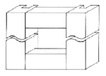
Take two of these corner pieces and place them side-by-side with the groove nearest the outside edge (ie furthest away from the other groove). Take the two front corner supports and place one at the top and one at the bottom of these corner posts, forming a square. Glue and screw the corner posts to these support pieces (see diagram). The resulting construction is the front of the left hand unit (ie the one that will have drawers in it).
Next, take two more corner posts and attach them to the switch panel thus forming a solid version of the above unit. At this time, cut a hole in the switch panel to accommodate the electrical switch that you have elected to use. You have now created the two front panels.

Cut all four plywood side panels to size. Two of these panels will be outer panels (ie physically located on the outside of the construction) while the other two are inner panels (see diagram). Take one outer and one inner panel and attach the drawer runners. These should be located at 1 1/4" to 1 3/4" (32 mm - 44 mm) and 2 1/2" to 3" (63mm - 76 mm) from the bottom of the panel, thus leaving a 3/4" (19 mm) gap between them (for the lower drawer) and 6" to 6 1/2" (152 mm - 165 mm) and 7 1/2" to 7 3/4" (190 mm - 197 mm) from the top. The drawers will slot into the 3/4" (19 mm) gap between the runners.
Take the two outer panels and attach the outer panel support to the inside of each one, so that it is flush with the top of the panel. This panel support should run from 1" (25 mm) from the back to 3/4" (19 mm) from the front. The reason for this support is to provide a wider, more solid plank of wood that the top of the router table can be attached to.
Take the two side pieces that you put drawer runners on. Attach the outer panel to the outer groove of the front left hand unit and the inner panel to the inside of the two grooves. To attach these, glue and nail from the side. Take one of the two remaining corner posts and glue/nail it to the back of the outer panel. Then, attach the top and bottom back spacers between this back corner post and the inner panel. The result should be a complete box (two sides and a front frame) that is the left hand unit. Repeat this exercise for the right hand unit.
To complete the base construction, it is necessary to join these two side units together with spacers. This is done by connecting both sides to a number of center support pieces (three for the base and three for the top). The top three should be connected (by screwing through from the side unit) at 2 1/2" to 3 1/2" (63 mm - 89 mm), 12" to 13" (305 mm - 330 mm) and 19" to 20" (483 mm - 508 mm) from the front of the unit. These should be aligned flush with the top of the side panels so that the top will rest on top of them. This is important as it will help stop the top from warping over time.
The bottom two supports should be attached at 1 1/2" to 2 1/2" (38 mm - 64 mm) -- ie just behind the corner posts -- and 19 1/2" to 20 1/2" (495 mm - 521 mm) from the front and should be flush with the base.
The result is one large box frame. Then, add the back panel to increase the strength of the frame. However, before you do this, cut out a square hole in the back panel that is 7" (178 mm) from each side, 3" (76 mm) from the base of the piece and 3" from the top of the piece (in other words, a square that is 9 3/4" x 5 1/2" (248 mm x 140 mm)). The purpose of this hole is to allow easy access (from the back of the table) to the router so that you can change the router bit.
Now it is time to build the top of the unit. Take the two pieces of 1/2" (13 mm) plywood (cut to 24" x 24" (610 mm square)) and attach them onto the frame made above. This should provide you with a top that is 1" (25 mm) thick. To attach this double thickness top to the base, use a combination of glue and screws. Make sure that the head of these screws is not above the level of the top Ñ they should (at least) be flush, if not slightly sunken in. Further. Do NOT use any screws in the area that will accommodate the router base. This sounds rather obvious but it is the most common mistake to make and is the cause of many a ruined router bit later in this project. To calculate where the router base will be, see below "Routing the base hole".
Once the top is secure (and the glue is dry) clean up the edges -- using a sander Ñ to ensure that they are smooth. Then, glue the formica onto the top (using special glue). This then needs to be left for approximately three days to ensure that it bonds correctly. Make sure that the formica sheet is slightly larger than the top plywood, so that it can overhang all four sides. By doing this, it is easier to align the formica to the top. Once it is glued securely you can use the router to trim the edges to make them flush.
Routing the base hole

It is now time to cut the hole for the router base. Obviously, the size of this hole depends upon the size of the plexi-glass router base you purchased. The sizes described below are based on the standard size of 11 3/4" x 11 3/4" x 3/8" (298 mm x 298 mm x 9 mm) that should be available from your local woodworking store.
First, mark out the full size of the area to be routed (ie 11 3/4" x 11 3/4" Ñ the same as the plexi-glass). The hole should be 6 1/8" (156 mm) from each side, and 1" (25 mm) from the front of the table. Then, rout out this area to a depth of 3/8" (9 mm). Take your time doing this, and take very shallow cuts initially so as not to splinter the formica. It is very important that you are accurate when routing out this area as you want to have a tight fit with the plexi-glass. To this end, clamp down straight pieces of wood as guides to ensure that the router cannot cut more than you want. When routing out this area you do not need to rout all of the square. Instead, rout out to a width of 3" (76 mm), leaving the middle of the square intact. By leaving this area intact you give the router an even, flat surface upon which to rest while routing out the remaining area.
Once you have routed out this area, mark out a smaller square that is 6 3/4" x 6 3/4" (171 mm x 171 mm) in the middle of the routed area, and cut this inner square out, using a jigsaw. This smaller hole allows the router to press up against the plexi-glass. Then, ensure that the plexi-glass fits tightly in the routed hole and that it is flush with the surface. Minor adjustments may be necessary to ensure that this is so.
Once the plexi-glass fits neatly, cut out the hole for the router bit and three screw holes in this plexi-glass. To cut these to the correct dimensions, remove the plastic base from your router and use it as a template. Do not throw this plastic base away as you will need to reattach it if you ever remove the router from the table. However, to attach the router to the plexi-glass, you should not reattach the plastic base as the new plexi-glass sheet becomes the router's new base.
Once these holes have been cut, make additional drill holes in each corner of the plexi-glass so that this sheet can be screwed into the router table.
Routing the measuring and back rest slots
Once the plexi-glass is complete, it is time to cut the slots that will accommodate the back rest bolts. These bolts run along two long slots (from front to back) so that the back rest can be easily moved to the correct distance away from the router.
Cut two slots Ñ one on each side Ñ that run all the way from the back of the table to within 7 1/2" (190 mm) of the front. These cuts should be 1/2" (13 mm) wide, and 3 1/2" (89 mm) from the side, running parallel with the side. As before, take your time and only cut a small amount each time. The depth of the cut (once finished) should be the same as the depth of the top (ie just over 1" in depth) so that the bolts can go all the way through.
Once this has been done, glue thin strips of formica to each side of the underneath of this slot. This will reduce the friction when sliding the bolt along the slot, thus allowing for easier movement of the back rest.
Once both slots have been cut (one on each side) it is time to cut the measuring slot. The purpose of this slot is to accommodate a thin metal ruler. These rules can be bought from any good tool shop and come as a roll. The rule is made of thin metal, with a self adhesive attached to the underside. While you could just glue this directly onto the formica, this would result in a slightly raised surface and would catch on any wood that you rout. To resolve this problem, cut a slot that is 1/32" (1 mm) deep and 1/2" (19 mm) wide (the width of the rule), parallel to the bolt slot. Again, this should run all the way from the back towards the front, with the front end stopping at 6 3/8" (162 mm) from the front of the table. [[NOTE: this front distance may vary from table to table. The point is that the tape should run up until it is flush with the front of the router bit]]. Stick the rule into this thin slot (using the self-adhesive backing), ensuring that 0" on the rule is at the front end of the slot.
Once all of the slots have been cut, attach the trim to each edge of the top. Adding the trim makes the top look deeper than it actually as, as well as improving the look of the table.
Building the back rest

The back rest is made of cherry, a relatively hard wood. You should pick a wood that is resistant to warping. Essentially, the back rest consists of two main pieces, the base and the front. Both pieces should be 24" long.
Take the base piece and cut a chunk out of it that is 1 1/2" (38 mm) wide and cuts back 1" (25 mm). This chunk should begin 11 1/4" (286 mm) from each side. By removing this small square of wood, the back rest will be able to overlap the router bit, allowing for very fine cuts to be made.
Next, take the front piece and cut out a chunk that is 1 1/2" (38 mm) high and 1 1/2" (38 mm) wide. Again, this should be 11 1/4" from each side (in other words, matching the base piece). Then, cut out four support pieces, triangular in shape, that are 1 3/4" (44 mm) wide and 2" (51 mm) long, with a 90 degree angle between.
Now all of the components are set, put every thing together. Glue and screw the from piece onto the edge of the back piece, and glue and nail the triangular supports between the two to strengthen the join (see diagram). The triangular pieces should be placed 1 1/2" (38 mm) and 9 1/2" (241 mm) from each side. Note that if you want to add a dust extractor to this router table, then the dust pipe will attach between the inner two support pieces and this should be borne in mind when deciding on the exact position of them.
Finally, cut two holes, 1/2" (19 mm) diameter, through the base piece. Each hole should be 1" (25 mm) from the back of the base piece and 3 3/4" (95 mm) in from each side (matching the slots cut in the table). These holes accommodate the two bolts that fasten the back rest to the table. Attach these bolts by pushing them up from the underside of the router table and then through the back rest holes. Use wing nuts to secure the bolts as this allows you to easily tighten or loosen the bolts as desired.
Building the drawers

Building the drawers is the easiest part of the whole project as they are not conventional drawers at all. These drawers are used to store the router bits and so do not need a back or sides. Instead, each drawer consist of a front and a base. Drill 1/2" (19 mm) deep holes in the base to accommodate the router bits and then glue and screw the front panel onto the end of the base.
Finally, attach a drawer knob to the front of each drawer.
Connecting the electrical components
As mentioned before, the router table has a switch on the front right side. This connects between the external power source (ie the house power) and the socket into which the router is plugged in. This socket should be attach to the inner wall on the right hand side (as opposed to the outer wall). Consult an electrical manual for details of how to connect up the wiring.
Warning: be very careful when wiring up the router table. Failure to adhere to local standards for wire type can potentially lead to a fire hazard or possible electrocution. It is therefore imperative that you consult with a manual or, if in doubt, consult an electrician.