 |
|
|
Adirondack rocking chair
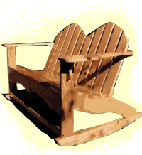
Due to popular demand, we have expanded upon the flippant comment at the end of the Adirondack chair feature and now offer the below description of how to make the two-seater rocking chair version. You will notice that the general methodology behind its construction is very similar to that of the standard Adirondack chair.
As with the standard chair, this rocker was constructed using pine, although a hardier, albeit more expensive, wood will provide many more years of enjoyment.
Construction
Tools required: Jigsaw, drill, sander, belt sander (optional)
Wood required:
| Description | Qty | Thickness | Width | Length | |
| Back legs | 2 | 3/4" (19 mm) | 5 1/2" (140 mm) | 30" (760 mm) | |
| Front legs | 2 | 3/4" (19 mm) | 3 1/2" (89 mm) | 21" (533 mm) | |
| Arm rests | 2 | 3/4" (19 mm) | 5 1/2" (140 mm) | 25" (635 mm) | |
| Front support (lower) | 1 | 3/4" (19 mm) | 1 1/2" (38 mm) | 44" (1,117 mm) | |
| Top Front support | 1 | 3/4" (19 mm) | 5 1/2" (140 mm) | 45 1/2" (1,155 mm) | |
| Seat slats | 11 | 3/4" (19 mm) | 1 1/2" (38 mm) | 44" (1,117 mm) | |
| Back support | 2 | 3/4" (19 mm) | 3 1/2" (89 mm) | 44" (1,117 mm) | |
| Back slats | 10 | 3/4" (19 mm) | 3 1/2" (89 mm) | 26" (660 mm) | |
| Middle seat support | 1 | 3/4" (19 mm) | 5 1/2" (140 mm) | 16" (406 mm) | |
| Rockers | 4 | 3/4" (19 mm) | 3 1/2" (89 mm) | 34" (864 mm) |
Take the two front legs and designate one end of each one as the top. Cut out a notch 5 1/2" (140 mm) long and 3/4" (19 mm) deep out of the front edge of each leg. This notch should begin 6 1/2" (165 mm) from the bottom of each leg. [So, measuring from the bottom, the notch should begin at 6 1/2" (165 mm) and end at 12" (305 mm).] This notch is used to slot in the Top Front Support which runs along the front of the chair (behind your legs once sitting in the chair).
Before fastening the Top Front Support into these notches, cut out the curve (or other desired shape) so make it look more interesting. I usually cut out two matching curves, side by side, to signify that this is a two-seater chair, as well as to match the back rest style. Once cut to the desired shape, glue and screw the Top Front Support into the two front leg notches. Ensure that these joints are square before putting the screws in.
Once the Top Front Support has been attached, finish of the front section of the chair by attaching the Front Support (lower). This should be attached level with the bottom of the two legs (in other words, at a height of 0" to 1 1/2" (38 mm) from the bottom of each leg), and is fastened into place by a screw (at each end) that is attached through each leg into the end of the Front Support (lower). Once attached, ensure that the completed front unit is square. This unit should now be left for several hours, until the glue has dried.
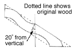
Next, take the two back leg pieces. Cut out the shape of the legs, as shown in the diagram (right). Note: the back support connects to the back legs 17" (432 mm) from the front of the chair. Cut the two back legs into a shape roughly resembling the diagram. I have not provided a more detailed diagram because it is really up to the individual (and the size of his/her posterior) to decide on the final shape of the seating area. Once you have cut out the two legs, use these as a guide and cut out the middle seat support. Note the line on the diagram that shows where the middle support ends. This is a rough estimate of the angle that needs to be cut at the back of the middle support. This is cut to a more accurate shape at the last minute, just prior to its attachment (see later).
Once the back legs and middle support have been cut to shape, attach the legs to the inside of the front leg construction (gluing and screwing from the inside outwards). At this point, the seating slats should be attached, thus forcing the back legs to angle correctly. To attach the seat slats, pre-drill each end of the slat with a screw hole, and then screw and glue the slats onto the back legs. Work from the front of the chair backwards -- leaving as little gap as possible between each slat -- until you have completely covered the 17" seating area (at which point, the back support will be attached).
The Back Rest
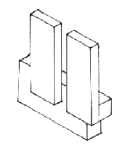
To build the back rest you should first construct the Bottom Back Support. Take the 3 1/2" x 44" (89 mm x 1,117 mm) piece of wood and cut a notch out of each end that is 3/4" (19 mm) deep and 2" (51 mm) high (see diagram opposite). Then screw and glue the ten back slats onto this back support, keeping them 2" (51 mm) above the bottom of the back support (so they overlap the back support by 1 1/2" (38 mm)). Once this is done, screw and glue the other back support onto the back slats at a height of 13 1/2" (343 mm) to 17" (432 mm) above the bottom of the back slats.

Once the back rest is dry, use the jigsaw to cut the back into a nice sweeping double curve. The highest point of the curve should be 26" (660 mm), while the lowest part (at each side) should be about 18" (457 mm) -- obviously, the exact dimensions are up to the individual. The highest points of the back rest should be slats three and seven, while the low points should be slats one and ten (the ends) as well as the meeting of slats five and six in the middle. Before the back can be fastened onto the body of the chair, it is necessary to cut the armrests to shape (see diagram left).
Cut the armrests to a shape as shown in the diagram. Again, the exact shape is up to you. Attach a small block of wood to the underside of each armrest at the back (see photo). Screw the armrests into the top of the front legs, leaving about 1" (25 mm) sticking back beyond the front legs. Then, attach the backrest by putting a screw through each back leg into the notched part of the back support.
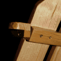
Finally, put a screw through the small lump of wood under the armrest into the upper back support. All that is then needed is to cut a small shaped piece of wood to support the front of the arm rest (where it meets the front leg) -- thus stopping it from bending when pressure is placed on it.
Once the back rest and arms have been added, you can attach the middle seat support. Cut the back end of the seat support to an angle matching that of the back rest (typically about 20 degrees from vertical) so that the seat support is flush against the Bottom Back Support. Screw and glue the seat support into place, exactly half way along the seating area. The support should be attached using screws running through the Top Front Support (2 screws) as well as through the Bottom Back Support (again, two screws). Once attached by the above four screws, the middle seat support should also be attach to the 13 seat slats, again using screws. This is important because it will help to distribute the pressure more evenly.
Building the Rocker
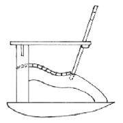
The final task is to build the two rockers. Each rocker is made up of two pieces 3 1/2" x 34" x 3/4" (89 mm x 864 mm x 19 mm) that are glued and screwed together. Cut each piece into the profile shown in the chair side profile above. Note that the front of the rocker has a more defined curve, while the back end is a gentle, longer curve, rather like the profile of an aeroplane's wing. This is important as it ensures that you will not tip over the back of the chair. Once you have cut the two pieces to their rough shape, glue and screw them together. Then, sand them into a smooth shape (this is best achieved using a band sander).
The rocker is attached to the legs of the chair at a distance of 1 1/2" to 5" (38 mm to 127 mm) from the front and 4" to 9" (102 mm to 229 mm) from the back. To attach the rocker to the chair, screw up from the underneath of the rocker into the chair leg. To make sure that the screw head does not show, drill up 1/4" (10 mm) using a drill bit that is slightly larger than the screw head, thus allowing the screw to be sunken well into the rocker.
Once the rockers are attached, the chair should be given at least two coats of marine varnish before being placed outside.